


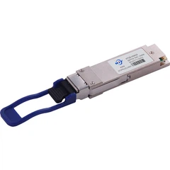




10Gb/s SFP+ 850nm Optical Transceiver Module HTSX-M8596Sx
Up to 11.3Gb/s data links
850nm VCSEL laser and PIN receiver
Up to 300m on 50/125µm MMF
Hot-pluggable SFP+ footprint
RoHS compliant and lead-free
Single +3.3V power supply
Compliant with SFF+MSA and SFF8472
Commercial: 0 ~ +70oC
Extended: -10 ~ +80oC
Industrial: -40 ~ +85oC
|
|
|
|
|
oC |
|
HTSX-M8596SC |
10.3125 |
850 |
300m MMF |
0~70 commercial |
|
HTSX-M8596SE |
10.3125 |
850 |
300m MMF |
-10~80 Extended |
|
HTSX-M8596SI |
10.3125 |
850 |
300m MMF |
-40~85 Industrial |
1. Absolute Maximum Ratings
|
|
|
|
|
|
|
|
TS |
-40 |
85 |
oC |
|
|
|
V |
-0.5 |
3.6 |
V |
|
|
|
Relative Humidity (non-condensation) |
5 |
95 |
% |
|
|
|
d |
5 |
|
|
2. Recommended Operating Conditions and Power Supply Requirements
|
|
|
|
|
|
|
|
|
T |
0 |
|
70 |
oC |
||
|
-40 |
|
85 |
oC |
|||
|
V |
3.135 |
3.3 |
3.465 |
V |
|
|
|
|
|
10.3125 |
|
|
||
|
|
2 |
|
V |
|
||
|
|
0 |
|
0.8 |
V |
|
|
|
D |
|
|
300 |
m |
50/125um |
3. General Description
HTF's HTSX-M8596Sx SFP+ transceiver is designed for use in 10-Gigabit Ethernet links up to 300m over Multi-mode fiber. The module consists of 850nm VCSEL Laser, PIN and Preamplifier in a high-integrated optical sub-assembly. Digital diagnostics functions are available via a 2-wire serial interface, as specified in SFF-8472.
HTSX-M8596Sx transceivers provide a unique enhanced digital diagnostic monitoring interface, which allows real-time access to device operating parameters such as transceiver temperature, laser bias current, transmitted optical power, received optical power and transceiver supply voltage. It also defines a sophisticated system of alarm and warning flags, which alerts end-users when particular operating parameters are outside of a factory set normal range.
The SFP+ MSA defines a 256-byte memory map in EEPROM that is accessible over a 2-wire serial interface at the 8 bit address 1010000X (A0h). The digital diagnostic monitoring interface makes use of the 8 bit address 1010001X (A2h), so the originally defined serial ID memory map remains unchanged.
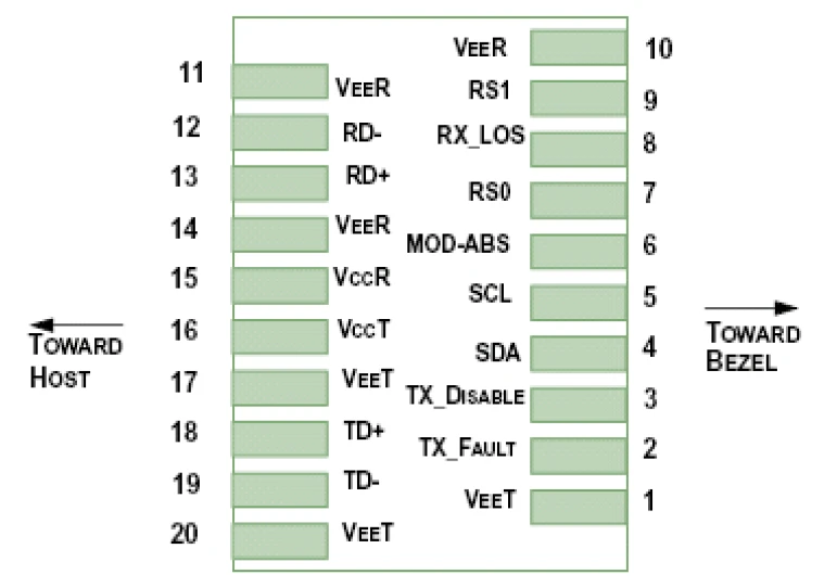
4. Pin Assignment and Pin Description
|
|
|
|
|
|
|
1 |
V |
1 |
|
|
2 |
T |
2 |
|
|
3 |
T |
3 |
|
|
4 |
2-wire Serial Interface Data Line |
4 |
|
|
5 |
2-wire Serial Interface Clock Line |
4 |
|
|
6 |
MOD_ABS |
4 |
|
|
7 |
RS0 |
Rate Select 0 |
5 |
|
8 |
Loss of Signal indication. Logic 0 indicates normal operation. |
6 |
|
|
9 |
RS1 |
|
|
|
10 |
V |
1 |
|
|
11 |
V |
1 |
|
|
12 |
RD- |
|
|
|
13 |
RD+ |
Receiver Non-inverted DATA out. AC Coupled |
|
|
14 |
V |
1 |
|
|
15 |
V |
|
|
|
16 |
V |
|
|
|
17 |
V |
1 |
|
|
18 |
TD+ |
Transmitter Non-Inverted DATA in. AC Coupled. |
|
|
19 |
TD- |
|
|
|
20 |
V |
1 |
1. Circuit ground is internally isolated from chassis ground.
2. TFAULT is an open collector/drain output, which should be pulled up with a 4.7kΩ– 10 kΩ resistor on the host board if intended for use. Pull up voltage should be between 2.0V to Vcc + 0.3V.A high output indicates a transmitter fault caused by either the TX bias current or the TX output power exceeding the preset alarm thresholds. A low output indicates normal operation. In the low state, the output is pulled to <0.8V.
3. Laser output disabled on TDIS >2.0V or open, enabled on TDIS <0.8V.
4. Should be pulled up with 4.7kΩ- 10kΩ on host board to a voltage between 2.0V and 3.6V. MOD_ABS pulls line low to indicate module is plugged in.
5. Internally pulled down per SFF-8431 Rev 4.1.
6. LOS is open collector output. It should be pulled up with 4.7kΩ – 10kΩ on host board to a voltage between 2.0V and 3.6V. Logic 0 indicates normal operation; logic 1 indicates loss of signal.

الوسم : sophos itfztchxf sfp+ 10g sr compatible optic transceiver, China, manufacturers, suppliers, factory, customized, buy, price, bulk, compatible brand, 100 جيجا هرتز DWDM SFP, 10G قابل للضبط DWDM 80km SFP في المخزون, 10gbase LR 10km SM CWDM SFP, مخصص 10G DWDM C النطاق جهاز إرسال استقبال SFP قابل للضبط, مضاعفات الألياف المزدوجة CWDM SFP, عام 10G DWDM SFP MODULE


